
Air-Insulated Disconnector (11–36 kV): Selection & Application Guide
Technical selection guide for 11–36 kV air-insulated disconnectors and load break switches — types, IEC 62271-103, visible break, earthing and application rules.

Technical selection guide for 11–36 kV air-insulated disconnectors and load break switches — types, IEC 62271-103, visible break, earthing and application rules.

Guide to 11–35 kV polymer (composite) insulators — silicone rubber weathersheds, IEC 61952, creepage distance, pollution classes and pin/post selection.

A 16-term MV distribution glossary covering expulsion fuse cutouts, air-insulated disconnectors, polymer insulators, reclosers and switchgear, with IEC references.

A complete technical guide to 11–35 kV expulsion fuse cutouts — construction, IEC 60282-2 ratings, dropout operation and selection for overhead MV networks.
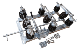
A pole-mounted air-insulated disconnector is only as reliable as its installation and maintenance. If the base is twisted, the contacts are loose, or the insulators are contaminated, the switch can overheat, flash over, or fail to create a safe isolation gap. This field guide covers the practical steps installers and lines crews need to follow when mounting, operating and maintaining 11 kV to 36 kV outdoor disconnectors on overhead distribution poles.
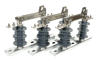
On medium-voltage overhead distribution networks, sectionalising and isolation are everyday tasks. A pole-mounted air-insulated disconnector — often called an off-load isolator or disconnect switch — provides a visible open gap so that lineworkers can confirm a line section is de-energised before maintenance. Because the insulation medium is air and the support columns are post or pin insulators, these switches are lightweight, economical, and easy to inspect in the field. The photographs below show two practical forms used on 11 kV systems: a single-phase porcelain double-break unit and a three-phase set with polymer insulators.
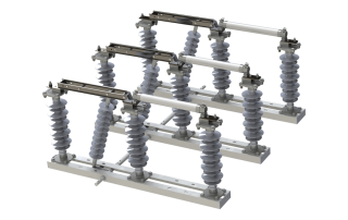
33kV Air-Insulated Outdoor Disconnector with Current-Limiting Fuses for Overhead Lines On medium-voltage overhead distribution networks, utilities need more than a [...]

Most cutouts that appear to "fail" in service were never installed to specification or were left without a maintenance plan. A device rated for 12kA breaking capacity is only as good as its mounting angle, torque, and the quality of the link fitted into it. This field guide covers what actually happens on the pole — from receiving inspection through commissioning, routine maintenance, and the step-by-step fault-response procedure. It is written for line crews, substation technicians, and EPC supervisors who install and maintain drop-out (expulsion) fuse cutouts on 11–35kV overhead distribution networks. For the underlying theory, selection math, and fault-diagnosis tables, see our companion technical article.
A misapplied or poorly maintained expulsion fuse cutout remains one of the most common causes of avoidable outages, transformer burnouts, and line faults across 11–35kV overhead distribution networks. This guide explains how the device works, how to size it correctly for your system, how to diagnose the faults that actually occur in the field, and the operating precautions that keep it reliable. It is written for utility engineers, EPC procurement teams, and maintainers specifying drop-out (expulsion) cutouts on medium-voltage overhead lines.